Linux Based Media Player
Update 2007: R.I.P
I was so close to finishing the project, but it was not to be. When I was moving, the movers must have put something heavy on it or dropped it, because the front was broken in half. The entire face is broken, missing buttons, cracks everywhere, really a mess. I could try to fix it, but it wouldn't look too good (plus some of the buttons would not work, like the "play" button), so I really don't think it's worth it. Shame, as the hardware was all done and tested. The only thing that was left to do was code the glue between the buttons and the media player (both worked, just needed to get them to work together). I'm really disappointed :-( .
That's life for you. There is one good thing though, when I moved in with my girlfriend, she had an old CD deck that would not play CDs properly, and said she would be happy to give it to me, provided that I let her help with the project, so a V2 might be in the works soon :-) (and if so, probably will be done faster as there are now two people willing to do it).
I'm leaving the article up, in case someone still wants to read it, but I am not going to do much to it anymore.
Introduction
Around 1999/2000, I stumbled across a site, Mini-Itx.com and was introduced to the wonderful array of projects there. The site isn't as good as it used to be, but when I first went there, it was amazing (to me) seeing computers fit into all sorts of things (other than the usual beige box). Once I saw this, I was spurred on to create my own Mini-Itx project.
But what to build? I pondered what I could use a silent PC for, and what case to put it in. While I was thinking away, my HiFi's CD deck broke down. This was a mixed blessing, as now I had an ideal case, but no way of playing my music CDs on the HiFi.
Also, I was getting tired of the noise coming from my big PC. I like to listen to my music collection (or internet stations) when I go to bed, and one thing that gets on my nerves is the constant whirring and whining of my big PC (not to mention that it is not the most energy efficient of beasts), so I thought a silent MP3/CD/[insert format here] player would be a nice thing to have. Coupled with the fact I had to listen to all my music through my PC now (the noise was getting to me), I decided on building the music player.
First thing I did was to google for similar projects, to see who else had attempted this. After quite a bit of googling, it became apparent that there were not many projects recently. There were a few back in the late 1990s, but nothing recent. I guess building standalone MP3 players is not in vogue anymore ;-)
Here is a list of some projects I came across (that still were accessible (lots of 404s) ):
MP3 O PHONO (1998)
M.A.P (1999)
Linux MusicBOX project (Note, in German) (1998)
MP3CD (A project very much like this one, NOTE: Horrendous amount of ads everywhere: it's a shame, because as it stands I found the site unusable).
Once I searched around, I decided to start on my project. The next thing to do was to define the project's goals (i.e. what did I actually want to achieve by doing this, and what would I like the end result to be).
After much deliberation, I decided on the following goals for this project:
- Support for all the formats I have in my music collection (including support for reading tags)
- This boils down to:
- MP3
- Ogg Vorbis
- FLAC
- All other formats are a bonus
- Playlist (.m3u or .pls) or disk scan support)
- This boils down to:
- Looks indistinguishable from the original
- I would like the interface to be not only easy to use, but to be exactly the same as the original, including things like:
- All existing buttons functional
- Buttons should do what the original labels say they do
- No new buttons having to be created
- The system can be minimaly used with just 4 buttons (Eject/load,Play, Stop, Next, Back)
- I would like the deck to look "stock", i.e. I want it not to give away any modifications done to it (from the front at least):
- No holes/other alterations on the exterior which would give it away (so no holes for cables/new buttons)
- Display area should stay the same (although the layout of the display can change)
- The rear should not give away the idea that there is a PC inside (so no VGA/PS2/etc.. ports visible)
- I would like the interface to be not only easy to use, but to be exactly the same as the original, including things like:
Of course, these goals are *ideal*, chances are that not all of them will be fulfilled, but I will strive towards them.
Note
I have been working on this project on and off since 2000. It has been 6 years, and (since the theft of my laptop circa 2006) most of the original pictures are no longer available, so in places there will mostly be text (though some pictures have been retaken). I also had to think quite a bit over how I was going to present this project. Doing it chronologically would have been a mess (as I have gone back and redone parts of it multiple times) so I decided that the write-up shall be split into stages.
Stage 1, gutting the CD deck
Well, the CD deck didn't work anymore, so I thought I would take it apart to see if I could fix it (admittedly, I didn't put much effort into this), and if not, to gut it. Removal and disassembly of the CD deck was not particularly interesting, so I will not go into the details here.
Unfortunately, due to my laptop being stolen, I don't have any pictures of the original disassembly.
After gutting it, it was found that there would be enough space to install a motherboard, CD-ROM drive and other required components, so the project was good to go.
Stage 2, reverse-engineering the input device
After gutting the deck, the next thing I did was disassemble the front panel. After dissasembly, I had the PCB (with buttons and VFD display) on its own.
To fulfill the "stock" goal, I would have to use the original deck face, so rather than having to fabricate my own PCB with buttons etc... I decided to see if I could work out how the original keypad/VFD display functioned.
The panel splits into three parts: the PCB (containing the circuitry), a plastic panel with the buttons moulded on it, and the metal front (which has the text above the buttons printed on it). The whole thing attached to the mainboard with a ribbon cable. The VFD is a custom built one with a layout like this: 00:00:00 (Track number:Time mins:Time secs).
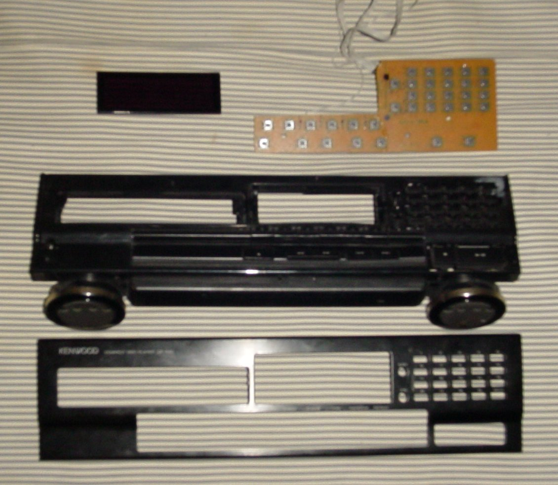
This picture shows the parts, from the top
1)PCB
2)Plastic panel
3)Aluminium facade
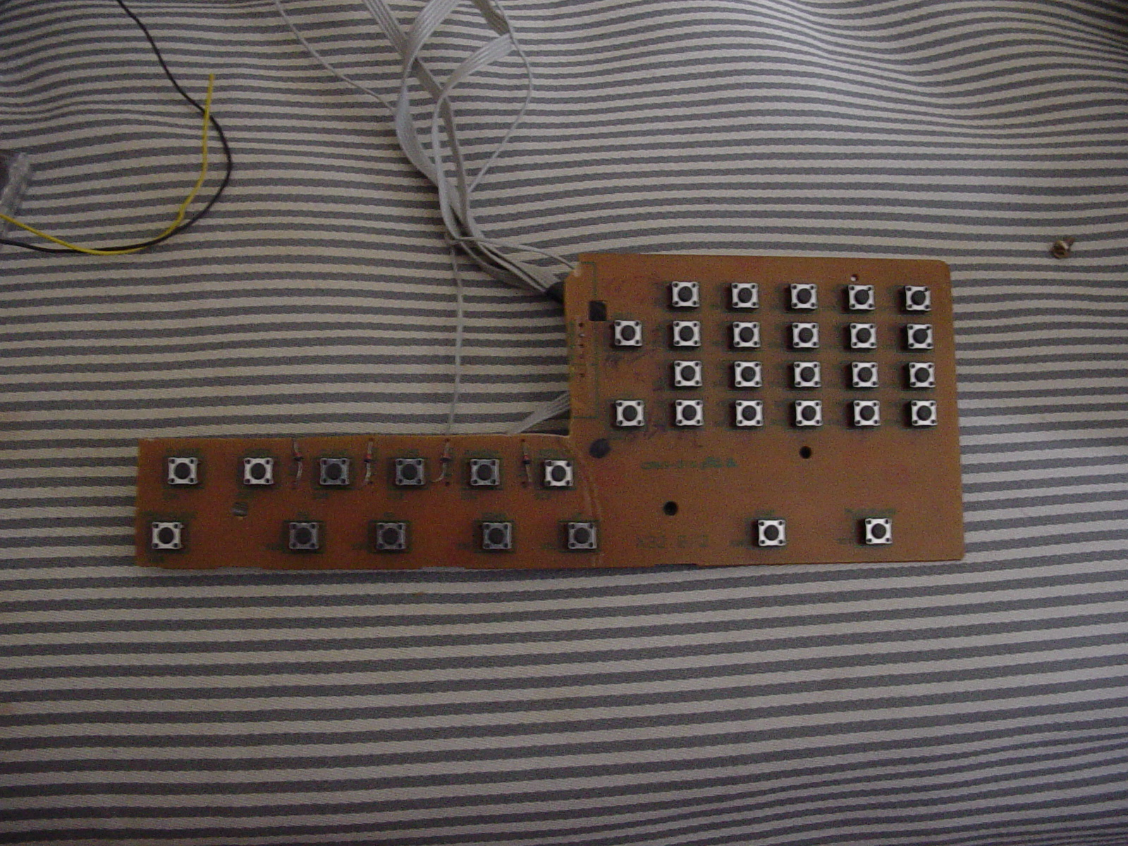
To build the keypad the first thing I did was remove the VFD, ribbon cable and other circuitry so that I just have the keys on their own. Once I did this, I looked at the buttons in order to spot any hints as to the connections.
Well, we knew that the buttons were connected to the same ribbon cable as the VFD, so I looked around that area for any connections (that did not go to the display) and lo-and behold, there were some. In a matrix, you need pull-up resistors on one face, and diodes on the other. This provided a hint as to where to start. If you look at the picture below, you see where the lines with diodes terminate:
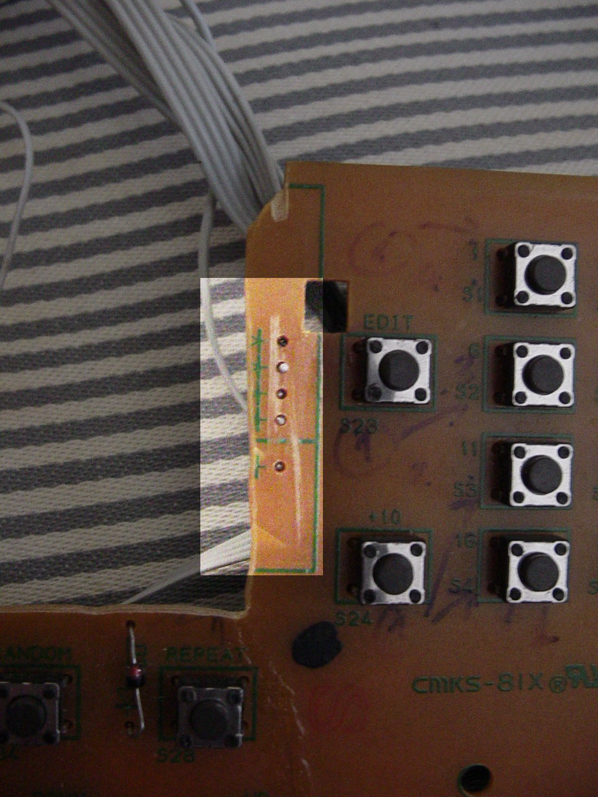
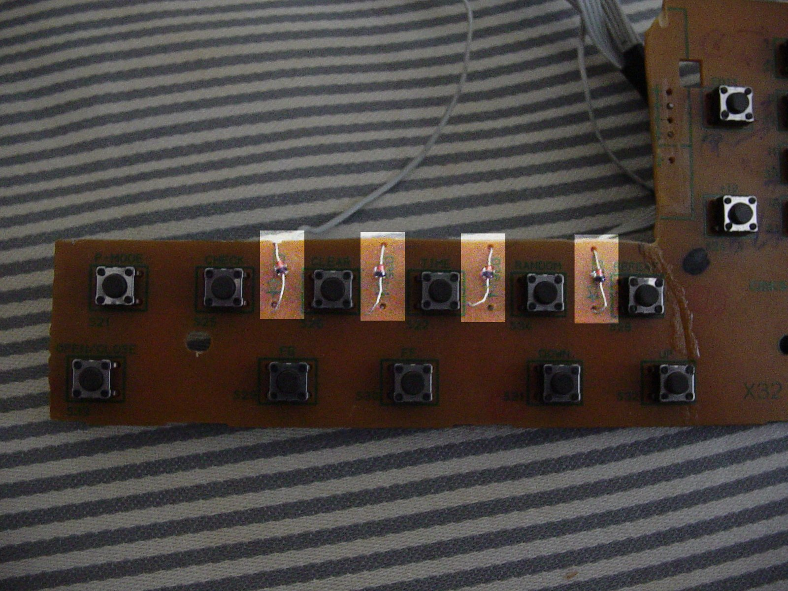
The two pictures above highlight the areas where the diodes were. (The first one has the diodes removed, but you can see the diode symbol ( -->|-- ), whlie the second has the diodes still connected)
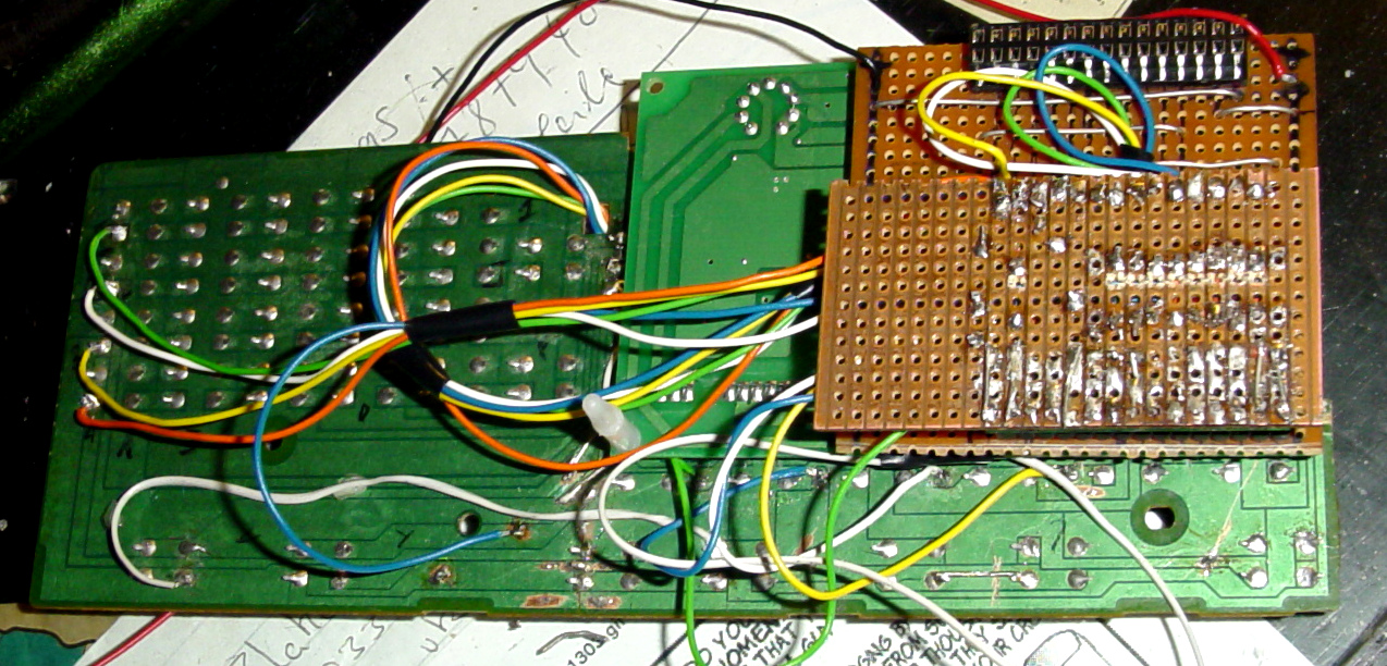
As you can see in the pictures, there are 9 of these lines. We know that there are 35 buttons. 35 / 9 = 3.88 = 4 (0 d.p). This meant that we needed to have 4 wires with a pull-up resistor in order for all the buttons of the matrix to work. Then we needed to find out where these missing 4 lines were. I took a multimeter (set to continuity tester) and put one probe on the known contact (starting from 1), pressed and held a button and poked along the other contacts with the other probe until I got a signal, then I marke along which line the button was. (The diode lines were numerically marked using a felt pen, from 1 to 9, and the four missing lines alphabetically "ABCD" as they were discovered). This would be done with each button in turn, and was very tedious and time-consuming, but by the end of it, I had the missing four lines, and every key mapped out according to an X-Y grid. Once I worked this out, I soldered wires onto the points:
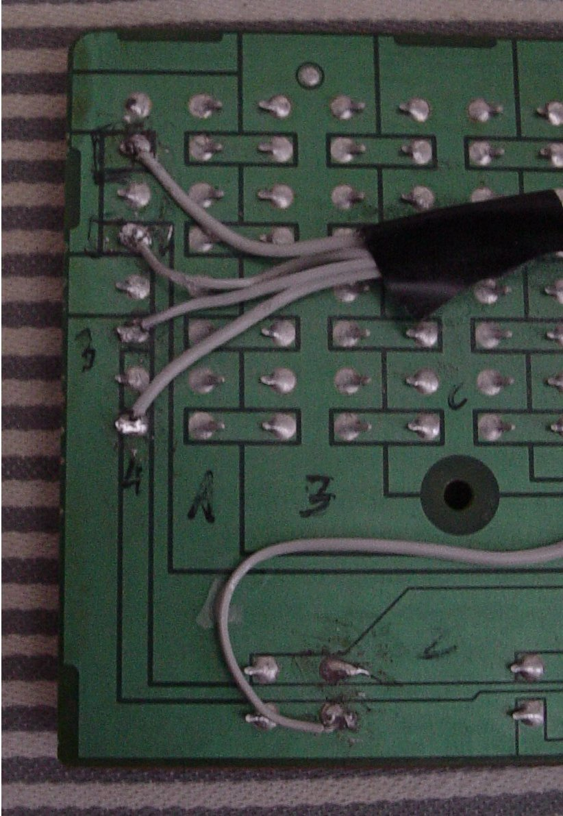
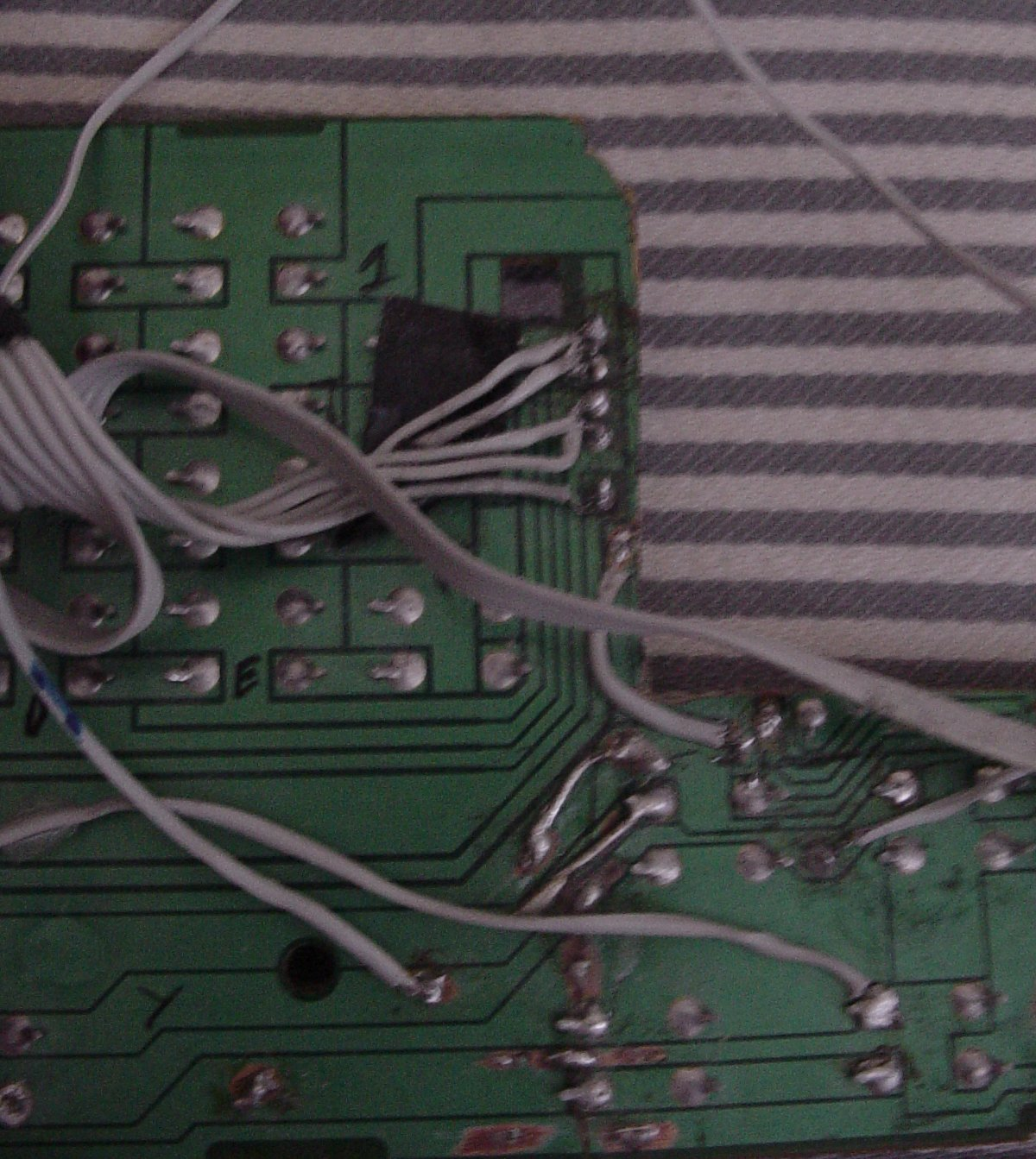
The connections made to the PCB, the first picture shows the 4 "hidden" lines we needed (complete with leftover black marker on the PCB from my probing). The second picture shows one of the strips with the rest of the wiring.
And the finished item:
Stage 3, building the input/output circuit
So now that we know how to interface to the keypad, we need to decide how to interface to the computer itself. We have a keypad and a display, which we want to interface to the motherboard. Rather than designing my own interface, I googled about to see if there were some already-established interfaces. Sure enough, there were quite a few, the most popular being the "winamp" 8-bit wiring, so I decided to use this one. The LCDproc page explained it, but didn't provide any schematics, so I did one myself:
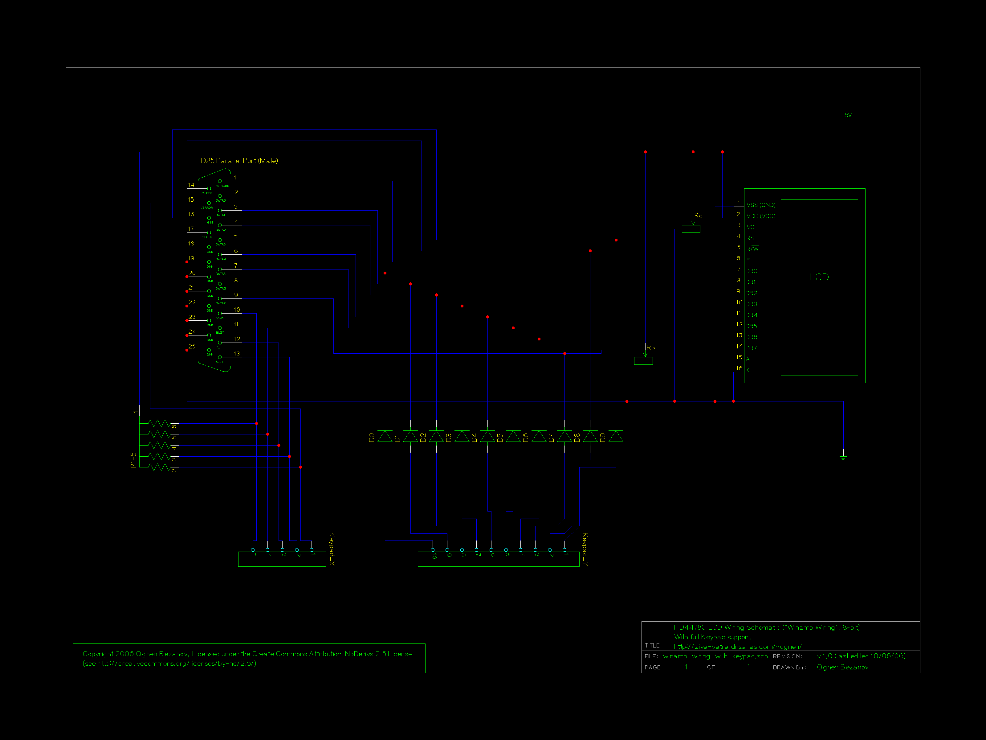
Also available as a gzipped postscript file
This schematic is a generic circuit (i.e. no modifications for this project) and as such has support for all the lines available via lcdproc, giving a total of 50 usable buttons (this project will not be using them all though).
I had a design, the next thing I did was to build a prototype circuit. Once that was done, I realised it would be best to have a full development platform.
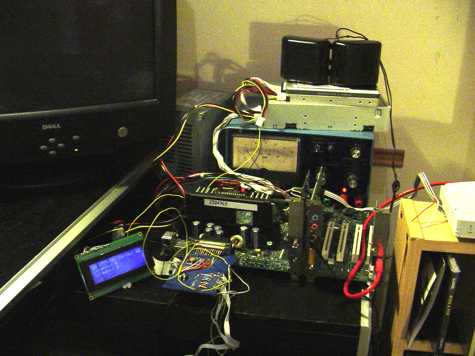
I could not write the program without any hardware to test/debug on, but I didn't want to spend money and time building the hardware for a project that may be fruitless. (This was quite a dilemma for me, which resulted in me postponing the project quite a few times). Eventually, I built a prototype using a PII(MMX) 233MHz Processor, Blue HD44780 LCD (with separate power supply) and keypad, 64MB ram, 500mb hard disk with Debian Linux and a crystal audio sound card (connected to pair of portable speakers), seen below:
The development environment:
Stage 4, the software
After much thinking, I decided to write my program in the Python language. This is because I wanted to learn to program in it, but was getting tired of the exercises that I did. I learn best when the need arises, so I thought this would be a rather challanging project to "jump in" with.
But before I did any programming, I had to plan out how I imagined this program would work. One of the most important things would be how the CDs it will read would be structured. Would the CD use playlists, or would it scan the files on each load. Would it be able to select groups of files to play via folders or playlists (if at all). After much deliberating I decided on the following:
- The player will be able to play audio CDs or data CDs with supported formats
- The player will by default make use of playlists, and if multiple playlists exist, the user will be presented with a menu-based choice
- If no playlists are found in the CD's root directory, then the player will scan the entire CD and play all supported media files
- Perhaps: We will able to browse in "disk mode", e.g. by folder etc...
I decided that scanning the CD for media files should be a last resort, because it's very slow (especially as we slow down the drive to make it quieter). Hence it will be primarily playlist-based.
That's the basic concept. The development environment mimics the end-system in interface but not in hardware, as such the development environment will only be a stepping stone, to see how well software development goes (i.e. so that I can work out whether it's worth continuing).
As for the software, I decided to leverage some existing open source projects. Most notably the lcdproc software, which is what drives the LCD display. I decided against writing my own LCD interface because a) the job was already done and b) lcdproc supports more displays than I will ever manage to. When comparing what software to use, I originally found that lcd4linux met more of my requirements (including split bargraphs, which I think is useful) and provided direct interfacing (lcdproc uses a client/server model over an IP-based network) but lacked the all-important keypad support. The idea of hacking together a keypad driver that would share the parallel port with another program felt too messy, so I decided upon lcdproc (and then found out that lcdproc already provided a menu system API which you could use, simplifing menu construction, which is great!). Other software I used are 3rd-party open source libraries (for the codecs in question) and of course, Linux, the operating system running all this.
The concept started out pretty simple, but by the end of it, I was programming a multithreaded python application, with all the issues that it brought up. I split up the program into modules, each one dealing with an aspect (interface I/O, audio decoding and playing, CDROM access, and the main one, which co-ordinated the rest). These were, in turn, split into classes. So far there has only been a requirement for three threads, one to deal with the audio decoding, one main one, and another one to deal with user input and display output.
The program was a success, as I got it to play ogg vorbis and MP3 files from a cd-rom, including displaying the relevant data on the LCD. Below are some examples of how the LCD interface improved with time:
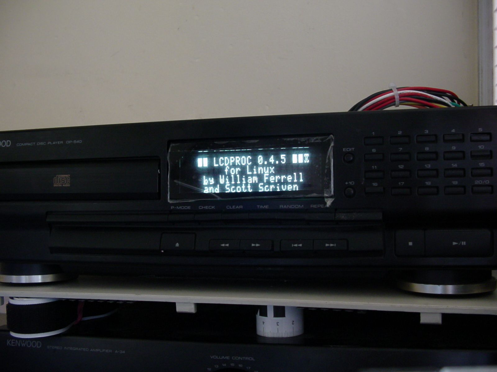
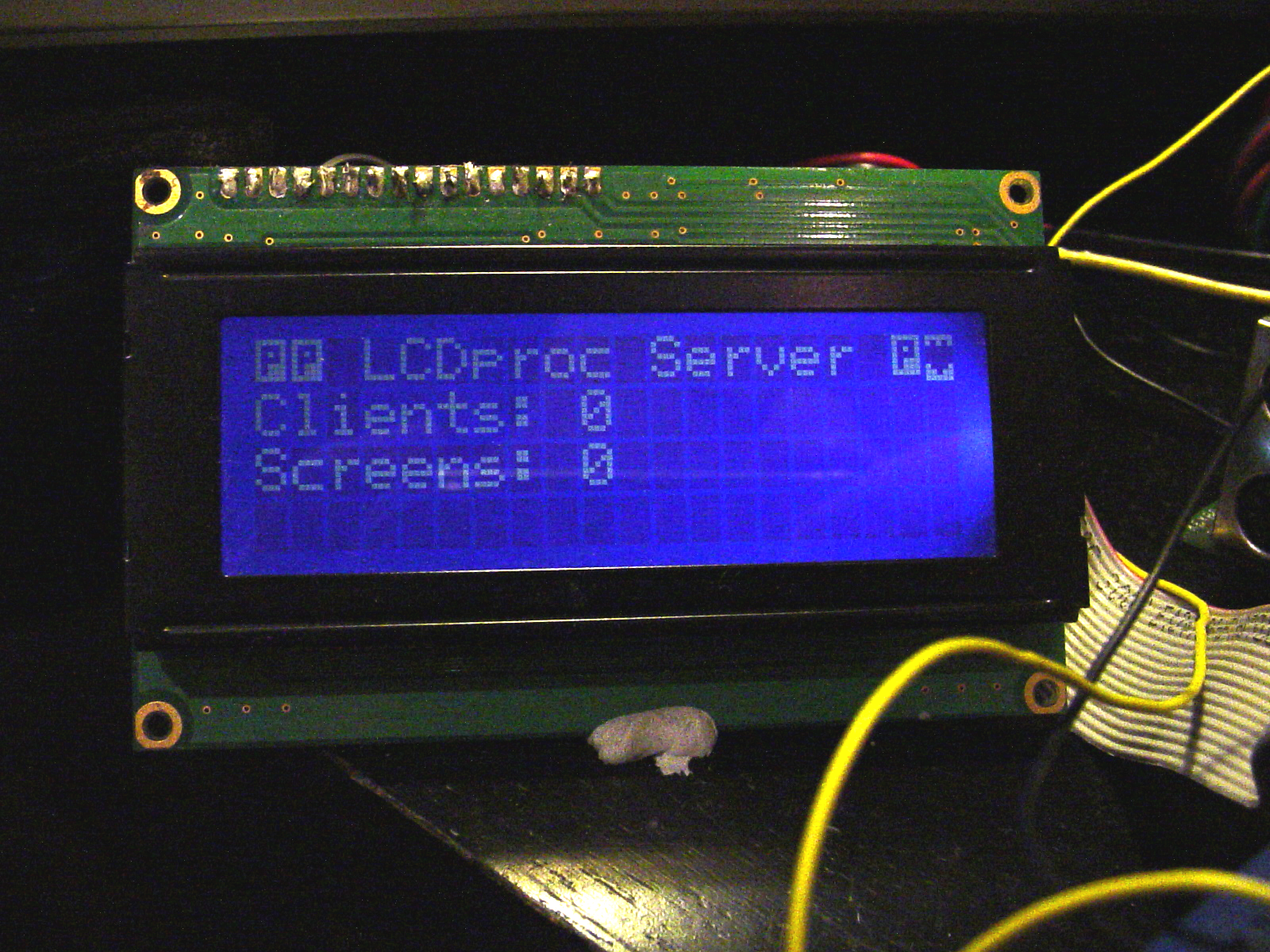
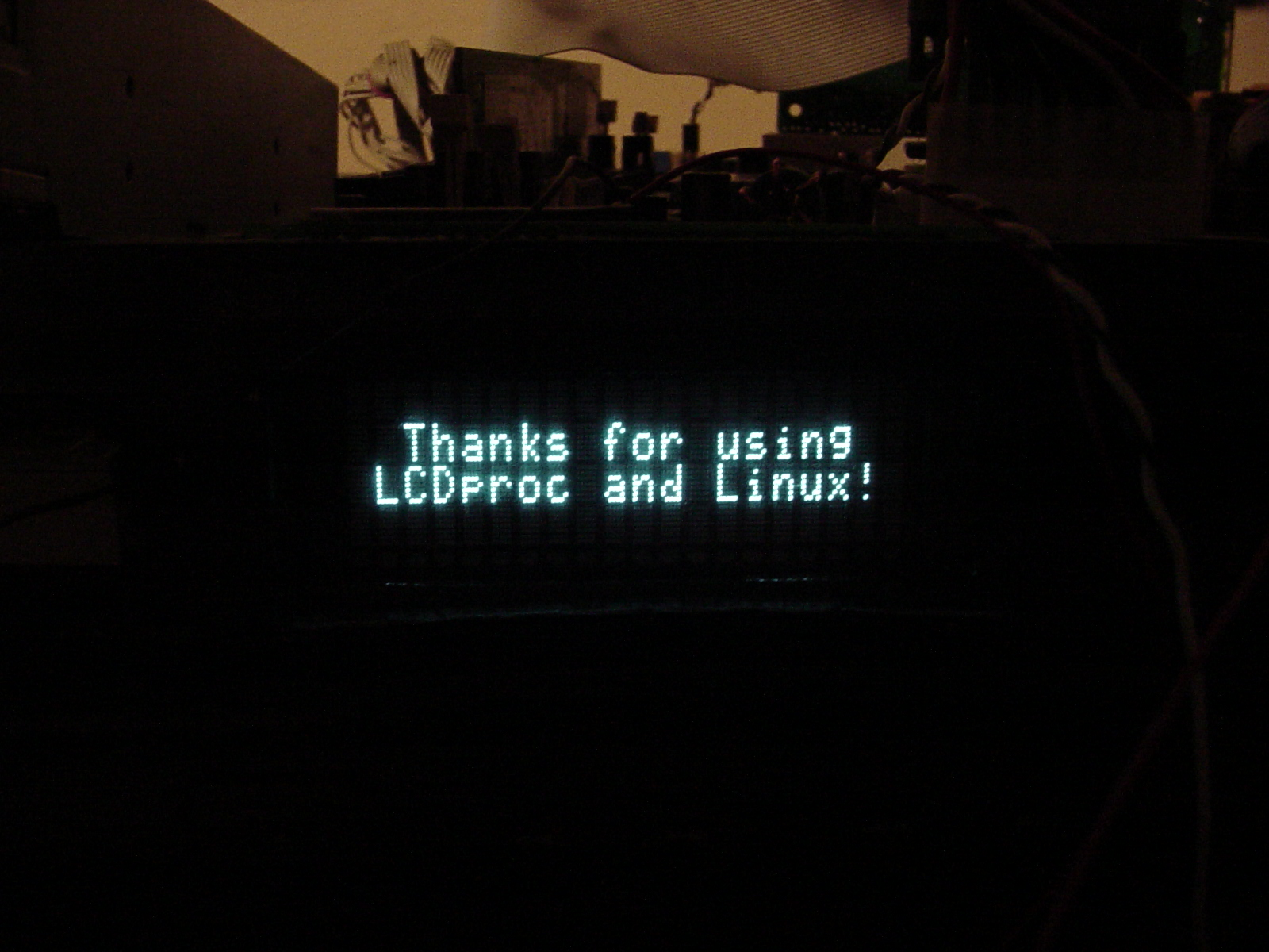
Initial LCDproc screen:
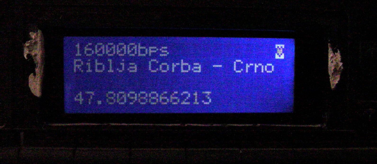
Below is the first draft of the interface, the first row is the bitrate, the second the Artist-Title and the fourth line holds the current time (in seconds):
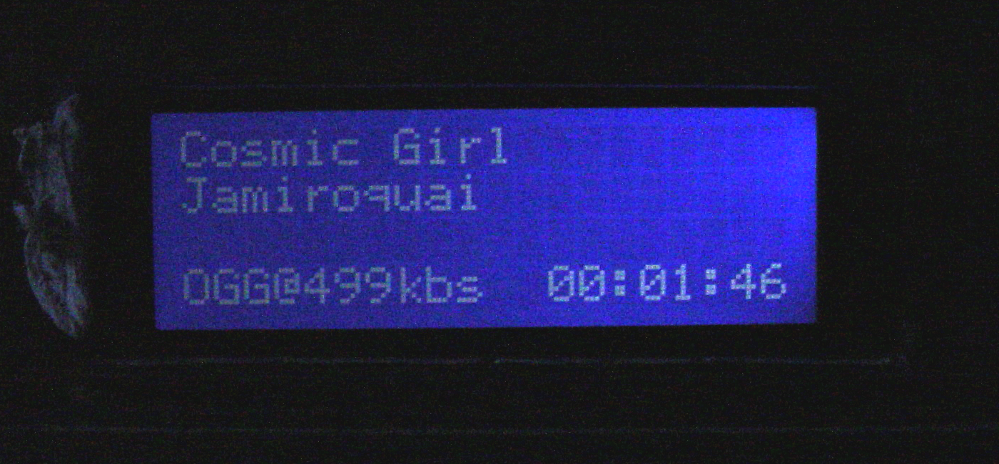
And the second version of the interface, with more user-friendly timekeeping, a bit more info and generally sorted out (we have more space in this interface, so the artist and title can have different names, so less need for scrolling):
At this point I decided to turn to building the proper hardware.
Stage 5: The Hardware
Motherboard:
This motherboard was donated by my girlfriend and I'm very grateful to her, as none of the motherboards in my possesion were acceptable for this case (those that did fit were overpowered and would overheat).
The motherboard as shown:
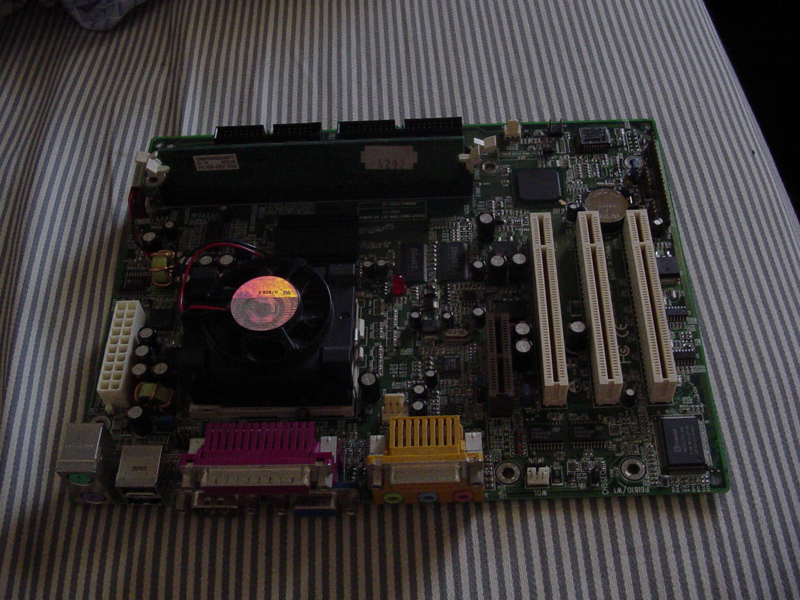
Ideally I would have liked a Mini-ITX Board, but they were way to expensive for me at the time, so this was the next best thing. It's a micro-ATX size motherboard (if I'm not mistaken) with a Via C3 Processor, 800MHz socket 370 (Same as on the VIA Mini ITX boards). I've never seen one of these CPUs before (Only Intel and AMD), so I took a picture:
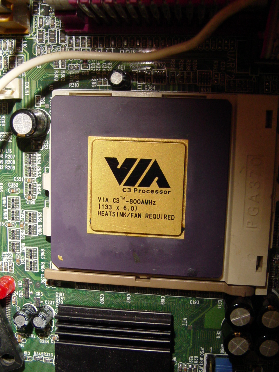
It is designed for low power consumption, so cooling should be much easier. The C3 in the mini-itx boards are fanless, so in theory, if I have a large enough heatsink it may be possible to omit the fan completely here as well. Unfortunatley though, not being a mini-itx board, this means I can't submit this project to mini-itx.com :-(
My girlfriend originally wanted this for another one of her projects, but she was nice enough to give it to me instead.
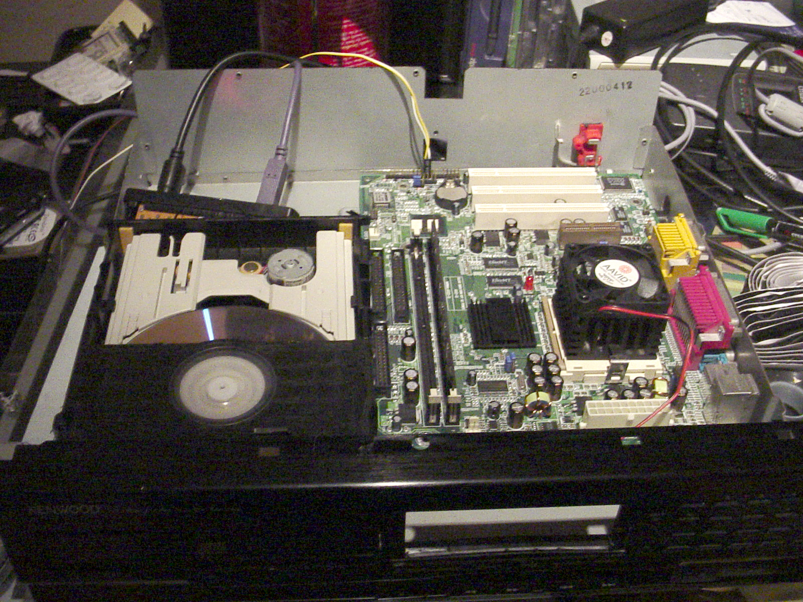
The motherboard was put in the case to see how it all goes together. It fits perfectly in case case. However the metal cover of the CD-ROM was just a few mm in the way, so it was removed. Now there are just a few millimetres between the CD-ROM Drive and the motherboard. The CD-ROM is currently hooked up via USB for testing (to make sure it works ok without the cover)
The Audio and LCD Wiring
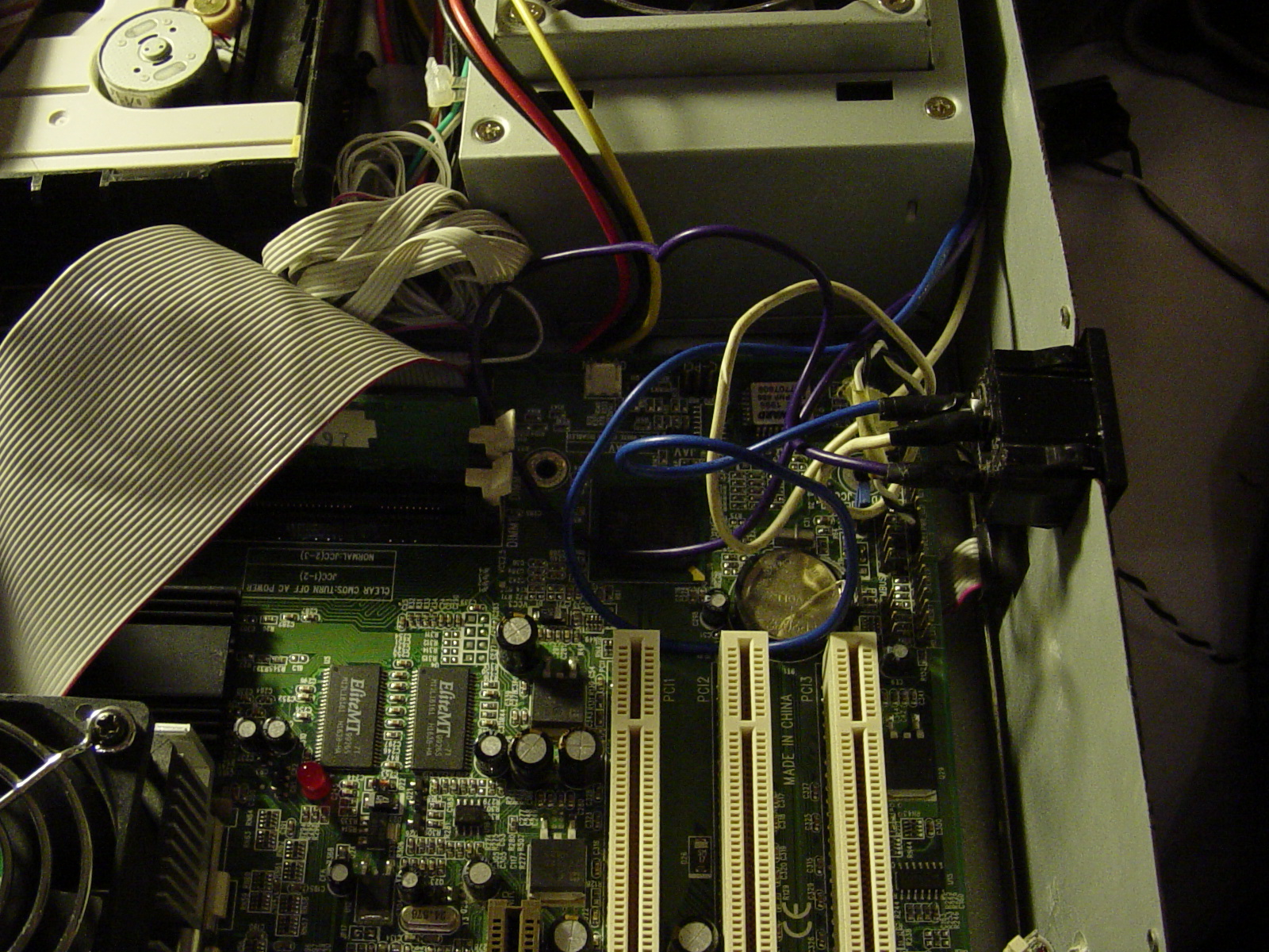
Once I settled on a motherboard, it was time to set up the peripherals. I needed audio out (for sound) and the parallel port (for LCD and keypad), but there was a problem: if you look on the picture above, you notice that the output ports face directly against the side of the case. There is no way of fitting any connectors there for my peripherals. The solution? I decided to wire them directly.
First I did the audio:
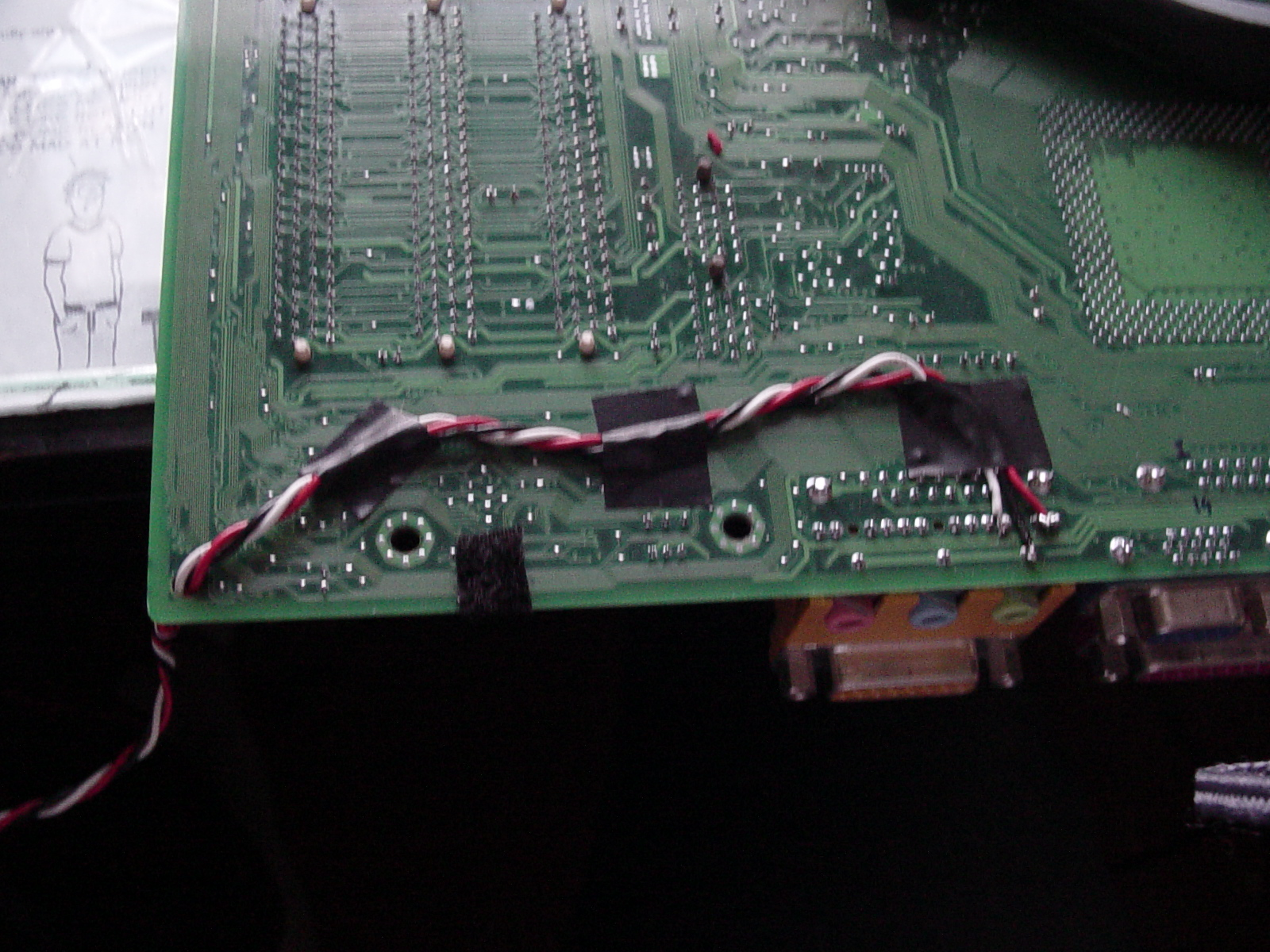
Three wires. Left, Ground and Right, for the audio channels. Once soldered, I threaded the cable out of one of the side hols for the sake of neatness. Next up, the parallel port:
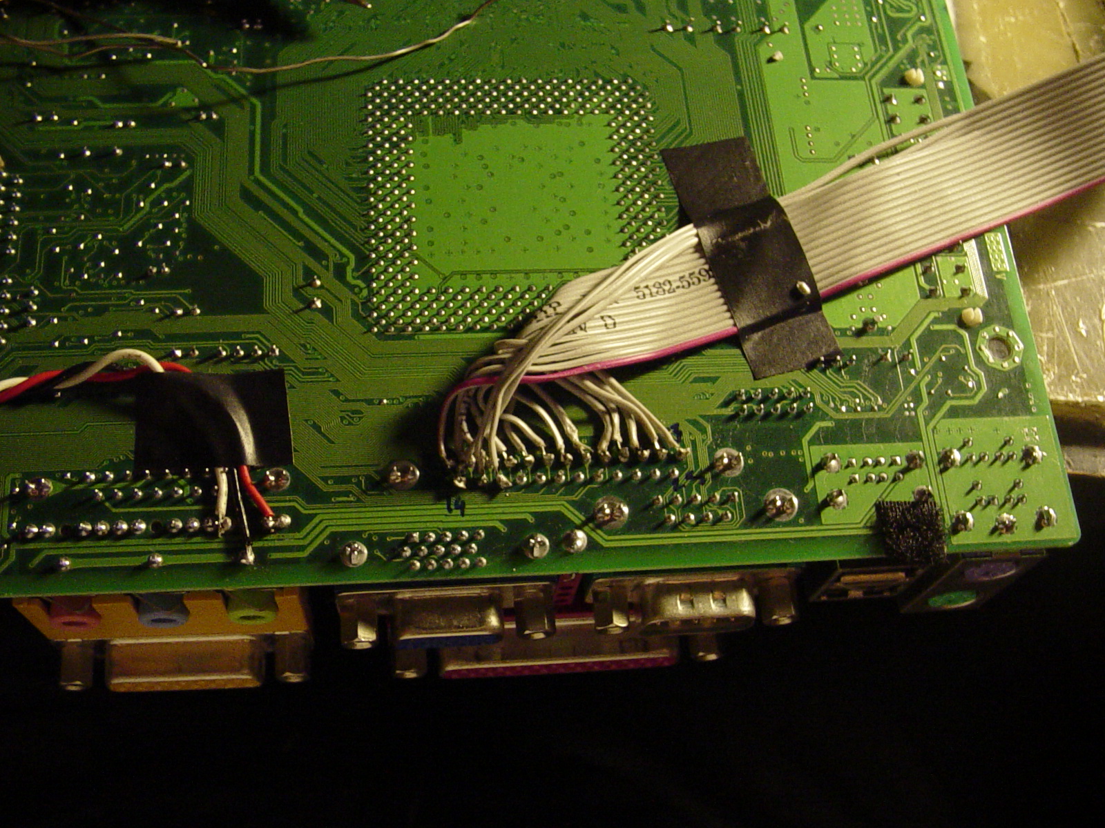
I used an old IDE cable for the connection, and only soldered the pins that I needed, rather than the whole port. The final result looked like this:
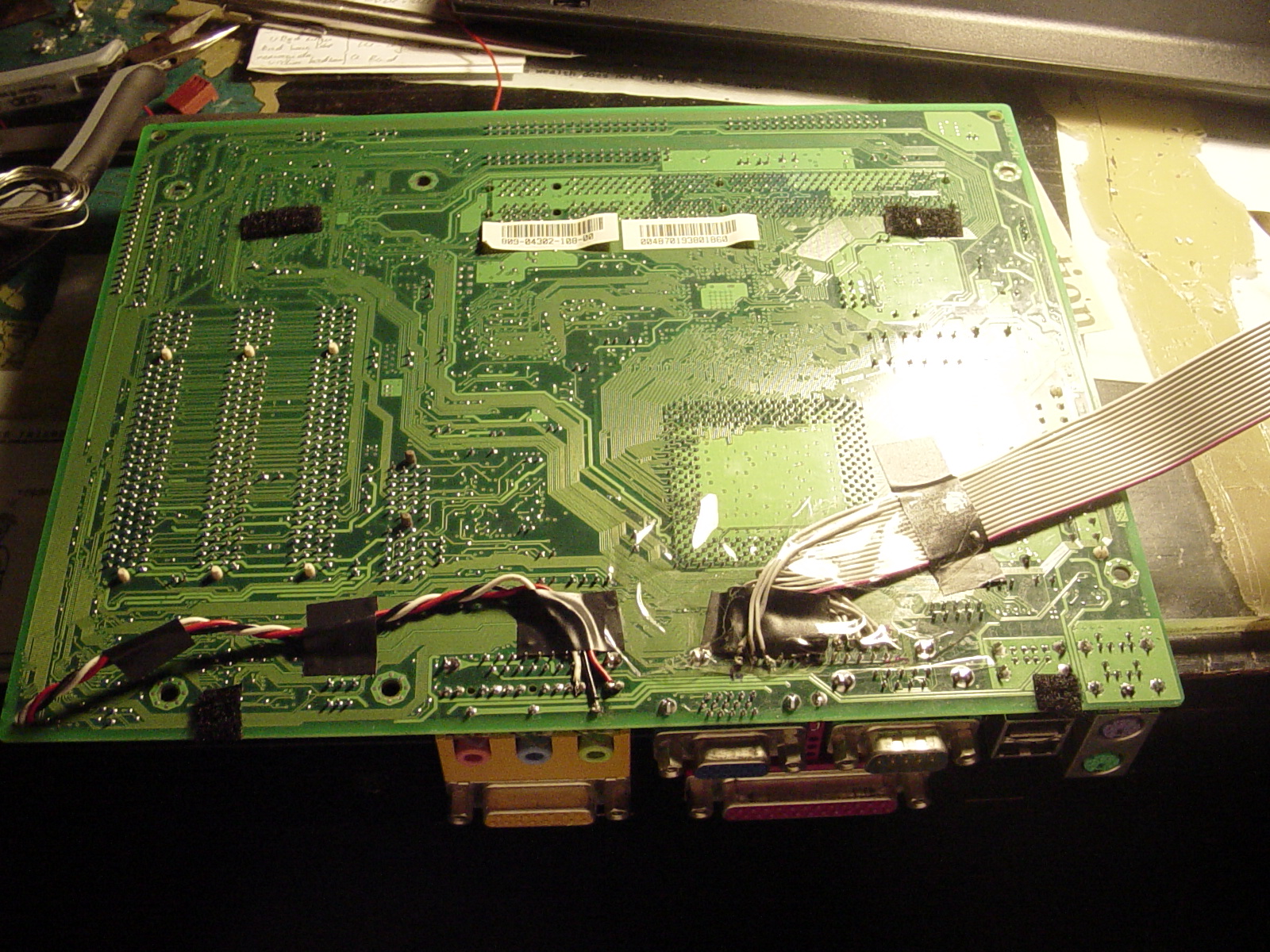
If you are wondering what the black squares are on the motherboard, they are velcro, which are used to stick the motherboard to the base so that it does not move. The soldered connections were covered with clear tape, to prevent short circuits against the case.
Serial port:
One thing I also wanted was a serial port, so I could have a console for debugging. This wasn't too bad, as the board had a pin header for it, I just connected a port to it, and threaded it out of the case (fittingly, the best hole for it was marked "System Control"):
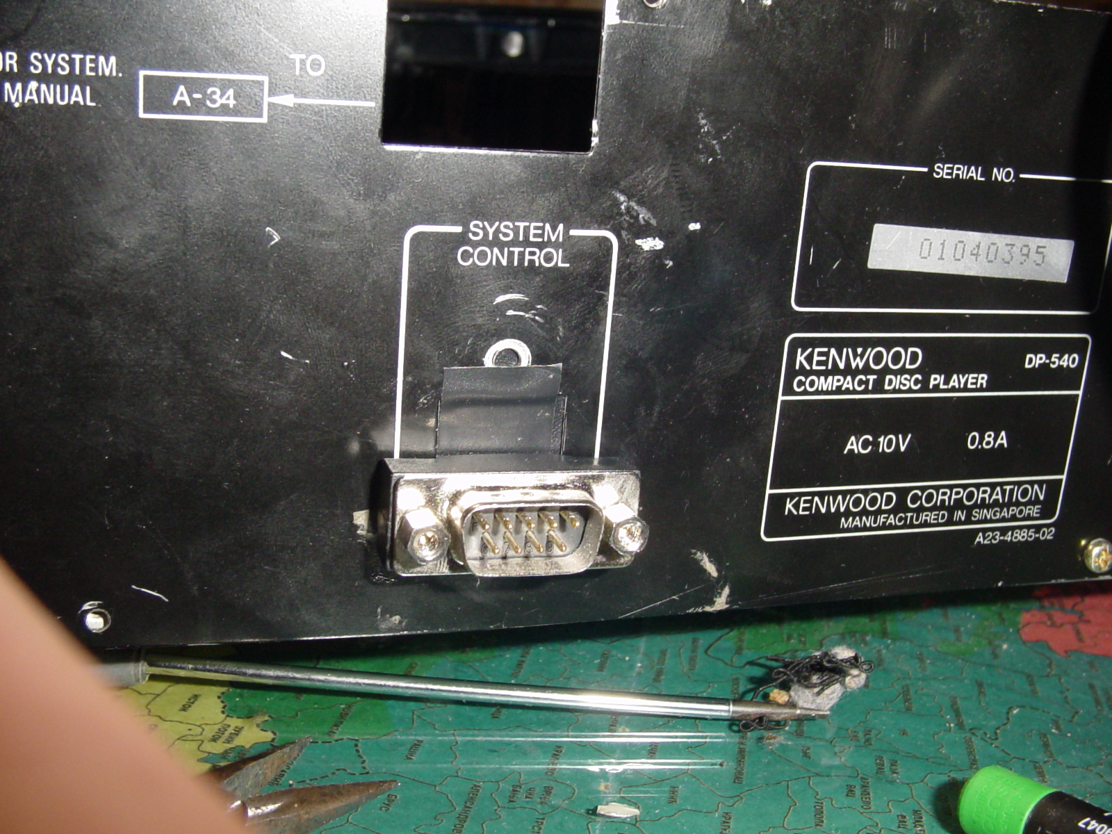
I will probably make it look better later on.
The LCD/Keypad interface:
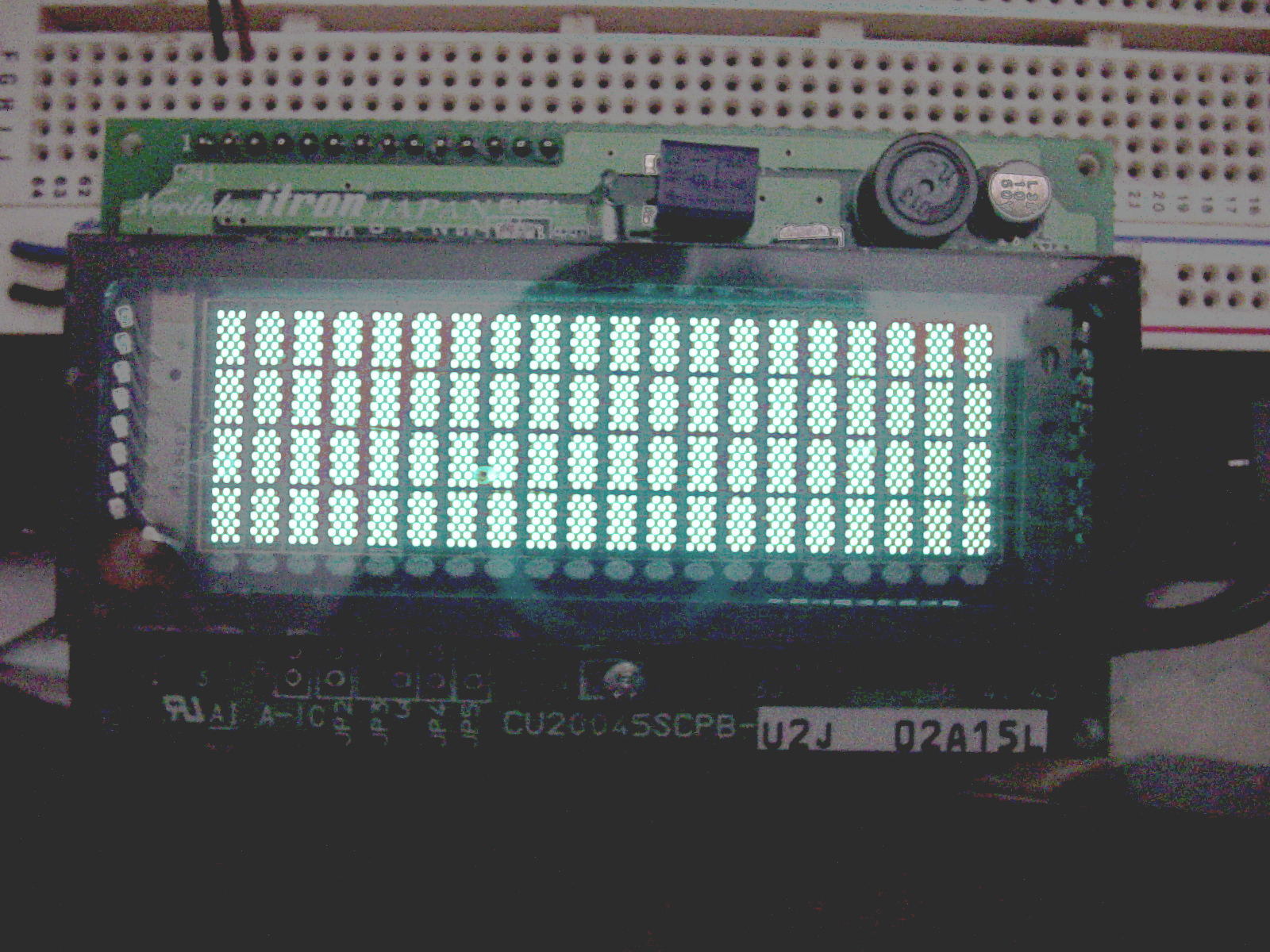
The last big thing left to do. When I was testing, I realised that, even at full power, the LCD could barely be seen through the glass front of the player. So I decided to get a VFD:
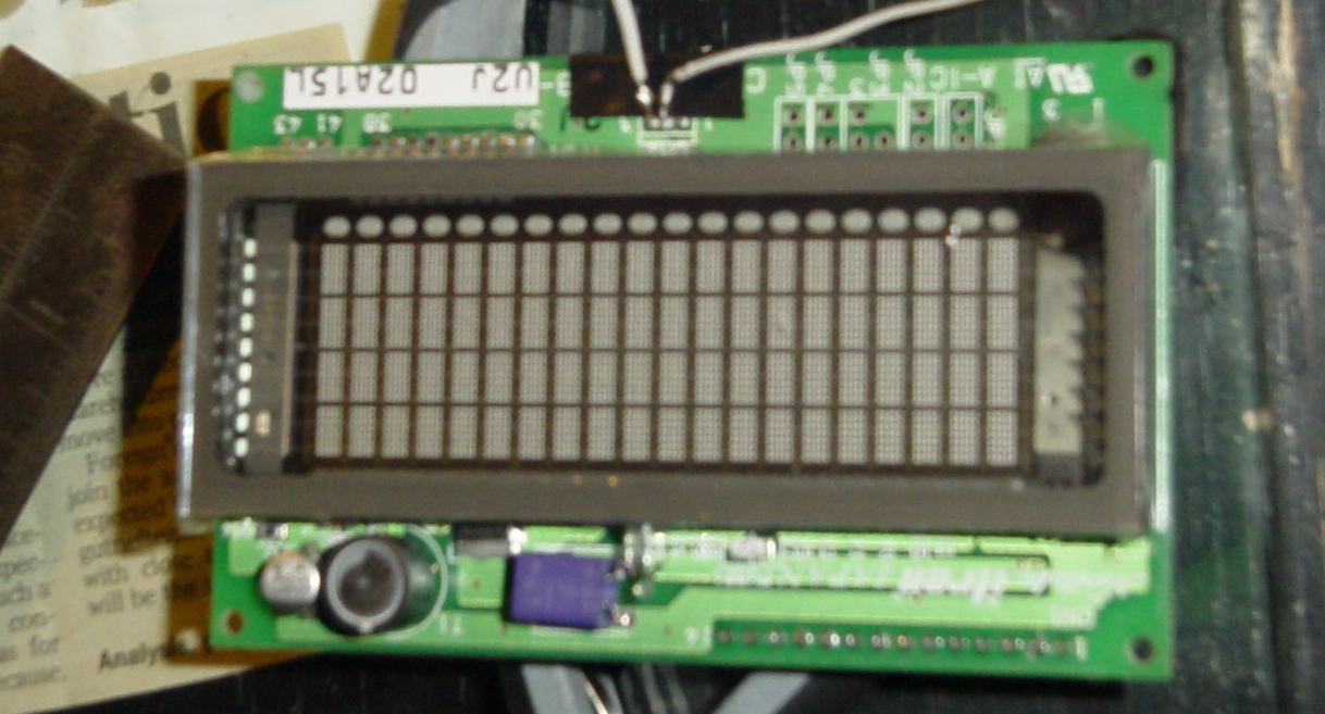
It is a Noritake itron. I got it off eBay for about £50, 4x20 LCD compatible (meaning it uses the same pinouts and signalling as the popular HD44780 command set) meaning it is a direct drop-in replacement. I had to remove a component and replace it with the wire in order for the VFD to fit in the space I had. Just run a quick self-test before continuing:
The first thing I made was the Parallel to VFD interface, unfortunatley I have no pictures of this since the theft.
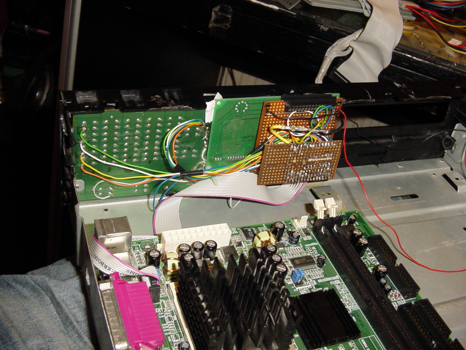
The second thing I made was the Keypad interface, which looks like this:
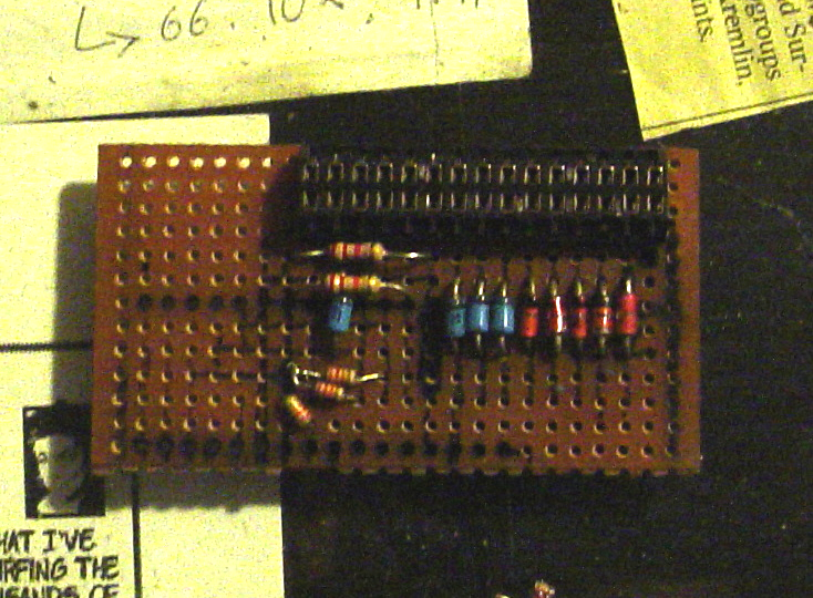
I decided to make the setup modular. So that it would be easy to replace different parts. There are two parts, which connect together. The first is the VFD interface, the second is the keypad and parallel port interface. You can see the two modules in the pictures of the finished item below:
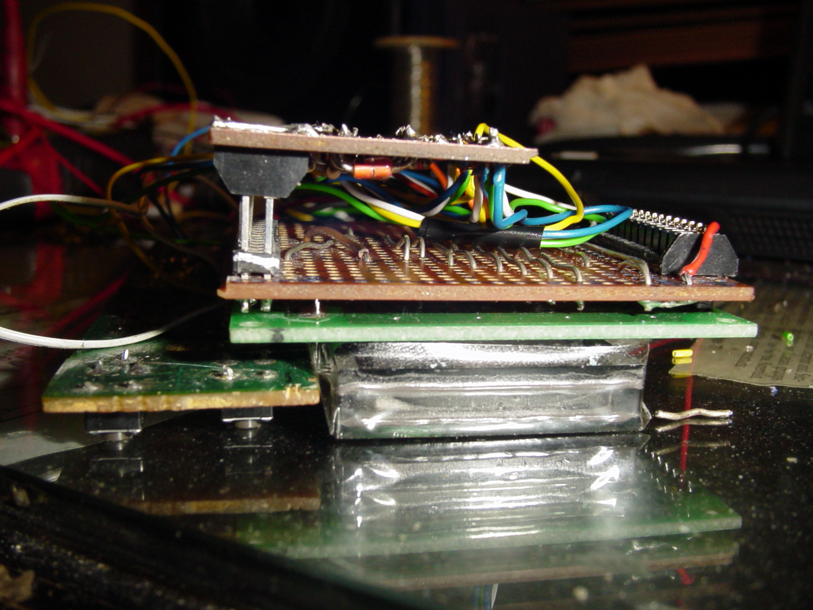
And the final result:
Installation:
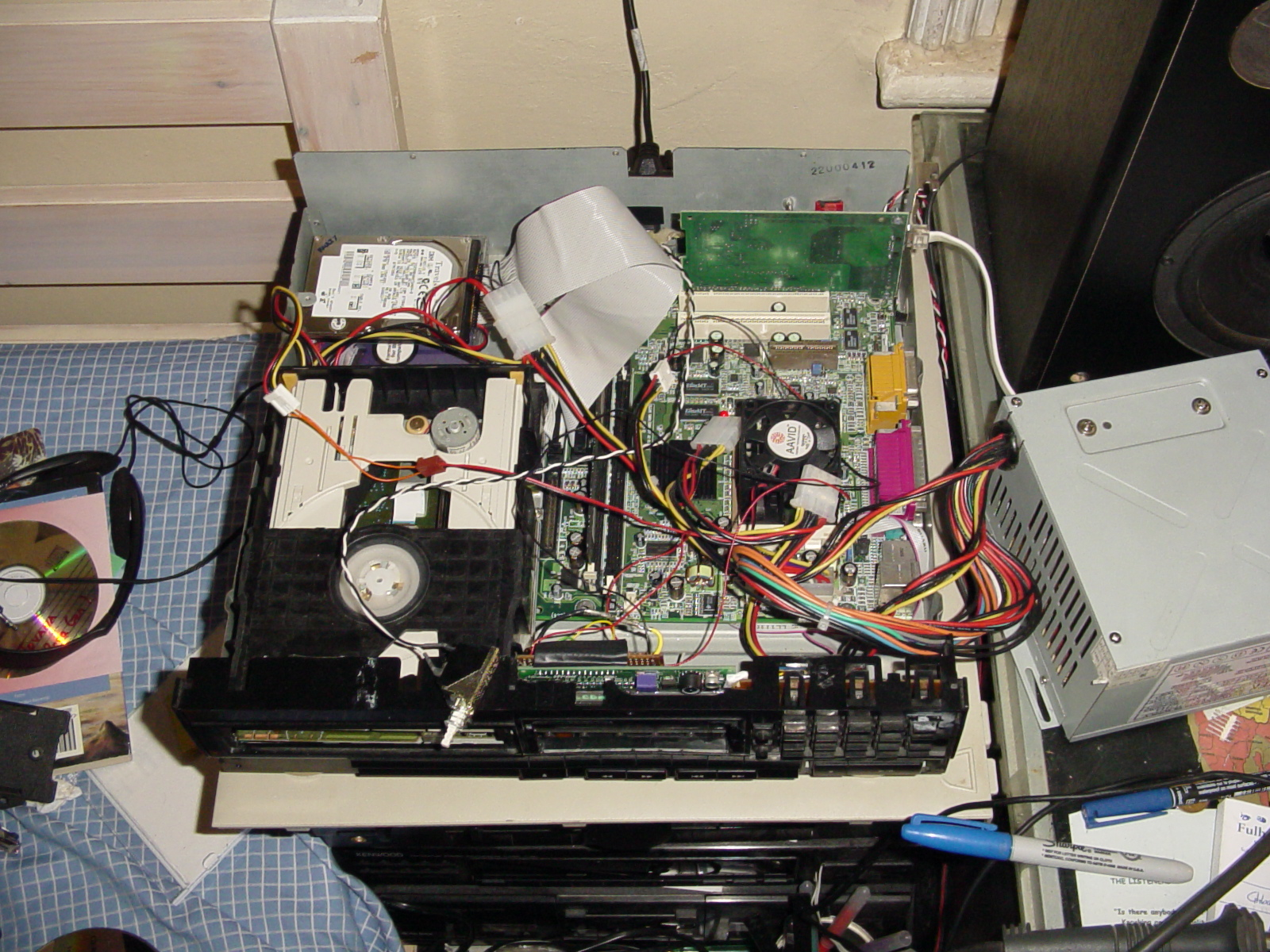
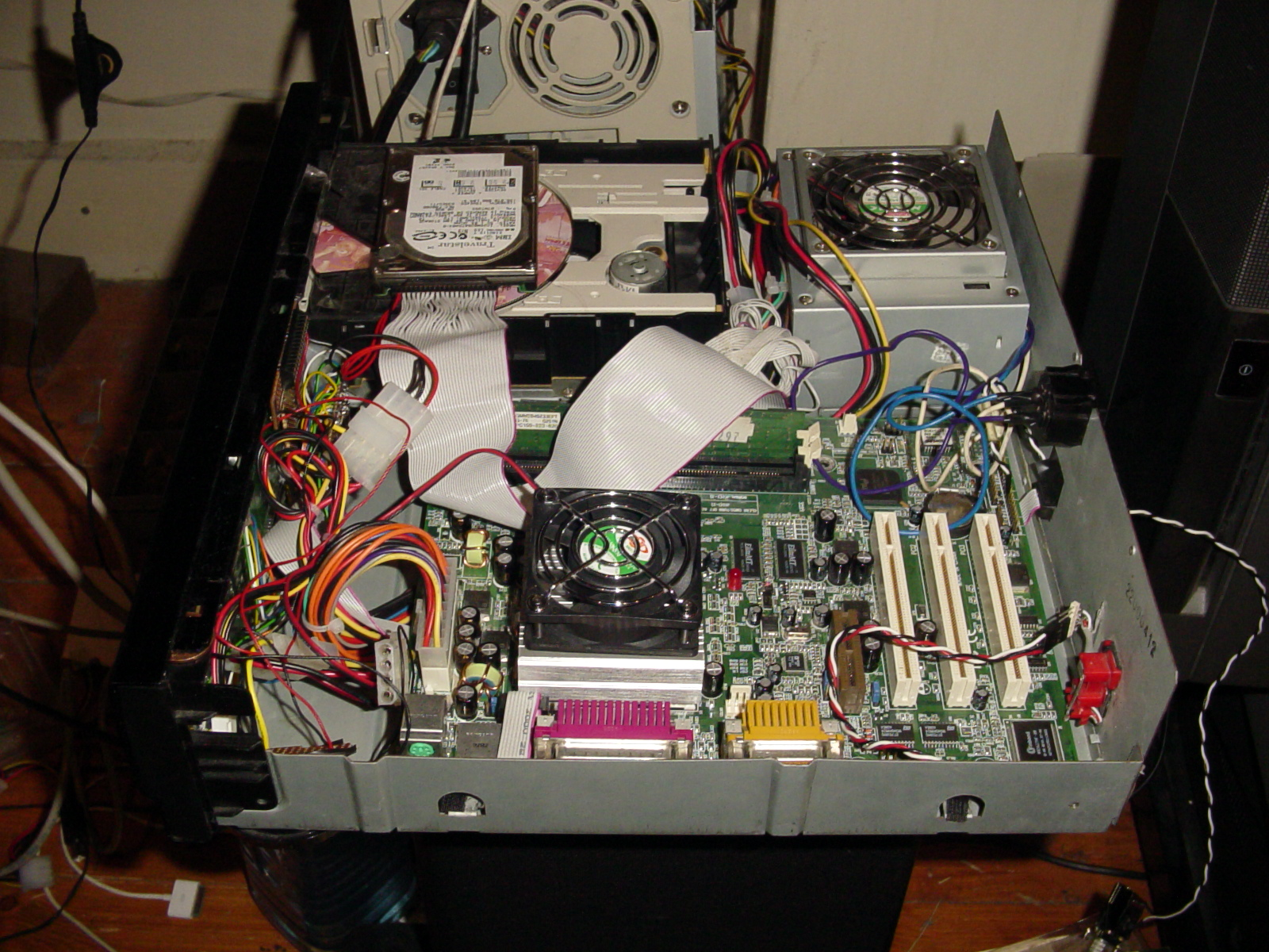
Well, with all the major parts done, now just installation left to do. First went the motherboard, then the interface:
And then, the CDROM, hard disk and all assorted wiring (the ethernet card was temporary, for testing). I didn't have a small enough ATX PSU for testing, so I temporarily hooked it up to a big one, as seen below:
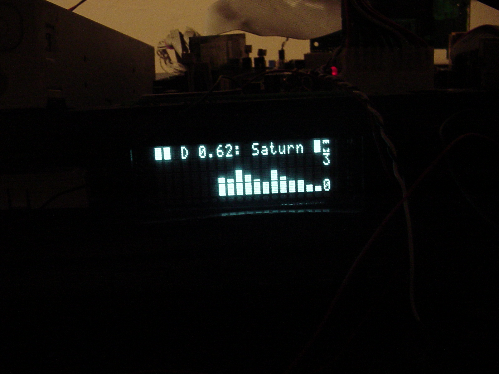
Turned it on for the first time, with success! The machine was working well, registering all button access and the display worked perfectly too. To give you an idea of how the VFD looked like, here are some pics (Saturn was the name I gave the machine during testing):
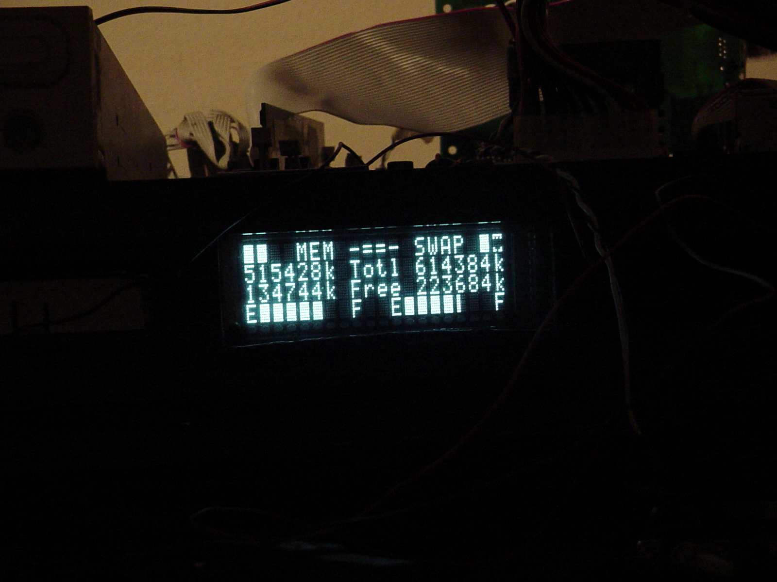
The PSU:
Almost finished! Only one thing left to do hardware wise, and that was the PSU. I found the Mini-ITX PSUs way too expensive, so I bought an 80W microATX PSU off eBay for £13. First thing I did was to remove the ATX mains connector and extend it, as shown:
I epoxied the base to the connector, so it would not move around. I also took a lot of care with the insulation, as getting a 240V shock when touching the HiFi would probably not be very pleasant.
And here it is, the final shot of the media player before I put the cover on (and probably tidy some wires):
The more observant of you may have noticed that different pictures had different heatsinks on the motherboard. I was trying different heatsinks, to try to make it fanless, but with the case closed it would get too hot. In the end I replaced the heatsink with a bigger one, and ran the fan at 5V. This proved to be a good mix, as it was silent but still moved air around. The PSU fans were quiet in the first place, so no modification was needed there. The hard disk is temporary for software development. Once I get the software up and running to my liking, I will switch the hard disk for an embedded Linux OS running on a CF card.
Final Integration
The end is nigh! With the hardware done, it was looking good, running well with no overheating. The only thing left to do was the keymap and software glue.
Well, on to the keymap. I had already wired the entire front panel to the LCD controller, but the numbers assigned to the keys were not very memorable.
The first thing I had to do, before I started, was to modify the lcdproc source, and the original lcdproc server did not support more than 10 keys in a matrix, with my modifications, you could attach 40 keys to the front, more than enough for this project (2007 update: lcdproc now supports this, so patch downloads have been removed).
Once I got lcdproc running, I wrote a little python program that would read the key that is entered, and print out its value. I sat there, pressed each and every key, noted down its value, then associated it with what the label underneath the key said. This was then fed back into the program, so it would start printing more friendly text, as shown in the example below (when the "18" key is pressed):
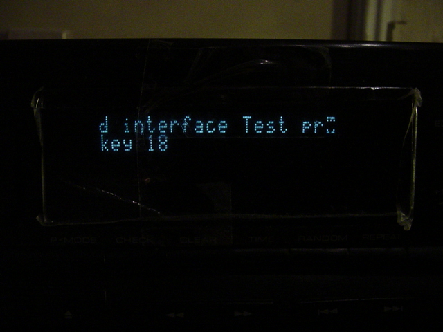
So I had the software, I had the thing decoding MP3s and ogg vorbis without issues, so all that was left was to put it all together. The first thing I did was decide on what my "idle" screen would be. I thought it would be nice if, when the machine isn't playing, it showed something useful, so after another quick lcdproc patch, I had bignum support for a clock. This way when there is no playing or no input on the player, it will show the time like this:
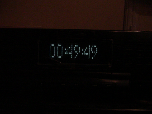
I thought it was cool, plus a lot easier to read from a distance than the other clock on the tuner (the picture doesn't do it justice, it is much brighter and clearer in real life). And yes, the time is not staged, I was up working on this project till about 2am.
Pause
I'm really happy with how the project is going, but I'm going to have to stop now as I'm moving soon, but as soon as I'm all set up in the new place, I assure you I will be eagerly continuing! :)


